This method describes how to determine the thousand kernel weight of malt.
Barley malt intended for use in beer brewing or elsewhere in the food industry.
The thousand kernel weight is more meaningful for evaluating malt quality than the hectoliter weight. A relationship exists between the thousand kernel weight and both the sieving test and the extract yield of malt, since the percentage of extract contained in malt increases with increasing thousand kernel weight, given that the protein content remains constant. The thousand kernel weight rises with increasing moisture content of the malt; therefore, it must be calculated in reference to the dry substance of the malt to produce an objective measurement [1].
This method describes how to determine the thousand kernel weight of barley.
Barley intended for the production of malt is evaluated on the basis of the thousand kernel weight.
This test is based upon determining the number of barley kernels in a subsample of a defined weight, i.e., the calculation of the weight of 1000 kernels of barley.
The method lists the equipment that is important in a brewery microbiology laboratory.
Microbiology laboratories in the brewing and beverage industry and their suppliers.
Membrane filtration unit incl. vacuum pump and suction filter bottle
Membrane filtration is used for the microbiological analysis of liquids that can be filtered. Microorganisms are retained by a sterile filter membrane with a pore size of 0.45 µm or 0.2 µm. The membrane filters are then transferred to culture media for anaerobic or aerobic microorganisms and incubated.
Membrane filtration units can consist of individual filter funnels or filtration manifolds with several filter funnels.
|
Fig. 1: Membrane filtration unit consisting of stainless steel funnel, frit and Woulff bottle |
Fig. 2: Membrane filtration manifold for processing multiple samples |
 |
 |
The main differences lie in the type of funnel used. Typically, stainless steel funnels are used, which are sterilised before use using a Bunsen burner or autoclave. Other common options are reusable plastic funnels that can be sterilised in an autoclave or sterile disposable filter funnels that do not require sterilisation at all.
A membrane filter station can be placed in the main laboratory as long as the filter lids tightly seal the funnel. In the case of plastic funnels, suitable or tight-fitting lids are not always available, in which case filtration should be performed in a clean bench. This prevents any contaminated air from being sucked in.
Anaerobic jars/anaerobic systems
Anaerobic jars are used to culture anaerobic microorganisms. A prerequisite is that the containers have a gas-tight seal and do not allow oxygen to enter.
An anaerobic atmosphere can be generated in different ways:
-
The container is evacuated using a vacuum and then flushed with an oxygen-free gas mixture
-
The containers are filled with reaction packs, which remove the atmospheric oxygen in the container or generate a CO2 atmosphere. Different systems are available depending on the manufacturer.
-
The anaerobic jars, which are flushed with gas, are fitted with two valves on the lid, which are intended for flushing and evacuating. A pressure indicator on the lid measures the pressure in the jar.
Anaerobic jars without gas flushing are easier to set up, as they only need to be tightly sealed.
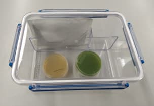
Fig. 3: Rectangular anaerobic jar for incubating anaerobic bacteria using oxygen-consuming chemicals
Anaerobic jars are available in metal, plastic and glass, with the glass and plastic containers having the advantage that the contents can be inspected from the outside without opening the lid, allowing you to identify an indicator change in the culture medium, for example.
Colony counters [1]
To count colonies on or in an agar plate, place transparent agar plates upside down on a flat, stable surface. It is important that the agar plate or its background is evenly illuminated without glare. It is also helpful to use a magnifying glass with 3-8x magnification or a stereomicroscope so that even very small colonies can still be seen. The counted colonies are usually marked with a coloured pencil on the underside of the Petri dish, or on the lid if using opaque culture media.
A more advanced method is to count colonies using a handheld colony counter. Here, the colony is counted using the tip of a pen, while the result is recorded on the LCD display.
A semi-automatic or automatic colony counter makes counting even more convenient and reliable.
Colony counters, although not all, offer three different ways of counting:
Counting by pressure:
This is the most common method, in which a coloured pen is used to lightly touch the (closed) Petri dish over the colony being counted. This marks the colony while pressing down slightly on the Petri dish; the pressure is transferred to a highly sensitive pressure plate, which triggers the counting pulse.
Counting based on electrical conductivity:
The Petri dish is open during the counting process. When a needle-shaped electrode is inserted into a colony, a current flows through the conductive culture medium to a counter electrode inserted into the agar at the edge of the Petri dish and this triggers the counting process. The method is unsuitable for (potentially) pathogenic microorganisms and is not recommended due to the risk of contamination.
Manual counting:
Counting in the conventional way by manually actuating a pressure switch in the appliance.
Cell counting using counting chambers [1]
The most common method for determining the total cell count in relatively high cell concentrations, e.g. pure yeast, is direct microscopic counting of the cells distributed in a counting chamber. The method is quick and requires little equipment.
The counting chamber method requires a relatively high cell concentration (> 107 cells/ml). In addition, the cells must be homogeneously distributed, immobile or immobilised and not be too small so that they can still be reliably identified under the microscope.
The counting chamber is a thick, flat-ground glass plate the size of a microscope slide, in the centre of which there are three parallel ridges ground crosswise, divided and delimited by grooves (Fig. 5).

Fig. 4: Thoma counting chamber
Source: https://de.wikipedia.org/wiki/Z%C3%A4hlkammer#/media/Datei:Neubauer_improved_counting_chamber.jpg (accessed on 17.11.2024)
Licence: https://commons.wikimedia.org/wiki/File:Neubauer_improved_counting_chamber.jpg?uselang=de#Lizenz (accessed on 17.11.2024)
The surface of the wider central ridge is ground to a precisely defined depth, slightly deeper than that of the two side ridges. A flat-ground, not-too-thin cover glass placed over the three ridges will rest only on the side ridges to create a hollow ("chamber") of a certain depth above the centre ridge.
The centre ridge is engraved with two square line grids separated by a transverse groove. The grid squares have a defined edge length and therefore a defined area, which means that the space above the square has a precisely defined volume at a known height. If this space is filled with a microorganism suspension and the cells contained in it are counted under the microscope, the number of cells per millilitre can be calculated.
Counting chambers with a depth of 0.02 mm are generally used for counting bacteria, while chambers with a depth of 0.1 mm are used for counting larger microorganisms such as yeasts.
The counting area consists of 16 large squares, which are bordered or separated by rows of smaller squares with an additional central limiting line. There are different versions of the Thoma chamber; the widely used old Neubauer version is shown here, consisting of 16 large squares. The improved Neubauer version consists of 25 large squares.
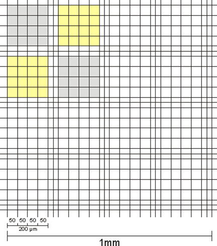
Fig. 5: General view of the counting area of a Thoma chamber (old Neubauer version)
Source: https://de.wikipedia.org/wiki/Z%C3%A4hlkammer#Z%C3%A4hlkammer_nach_Neubauer (accessed on 19.10.2024)
Licence: https://commons.wikimedia.org/wiki/File:Neubauer_classic_center_square.gif?uselang=de#Lizenz (accessed on 19.10.2024)
The cell count per ml of undiluted microorganism suspension is calculated using the following formula:
\(\text{cell count/ml}=\frac{\text{Total number of counted cells } \times \text{ dilution factor } \times 4 \times10^8}{\text{Number of small squares counted }\times\text{ chamber depth in µm}}\)
The method lists the equipment that is part of a sophisticated set-up in a brewing microbiology laboratory. This additional equipment is less common, but should also be mentioned.
Microbiology laboratories in the brewing and beverage industry and their suppliers
Light microscope with fluorescence
Fluorescence microscopy is a light microscopy method that utilises the physical effect of fluorescence. UV or short-wave visible light of certain wavelengths (excitation light) is absorbed by fluorescent substances and emitted as longer-wave radiation (emitted light) as a result of the Stokes Shift. In contrast to bright-field microscopes, the image is only produced by the emitted light. Fluorescence microscopes are therefore only suitable for samples with inherent fluorescence or for samples into which fluorescent substances can be introduced.
Design and mode of operation:
The desired wavelength is filtered out of a light source using an excitation filter and projected onto a dichroic mirror. Dichroic mirrors only reflect light below a critical wavelength. Above this wavelength, light can pass through the mirror. The excitation light reflected through the objective to the specimen is then absorbed by the electrons of the fluorescent substances. As a result, these reach a higher energy state. However, due to the instability of this state, the electrons revert to their ground state, releasing the energy they have absorbed. The resulting emission light is lower in energy and therefore has a longer wavelength. This longer wavelength emission light reflected by the objective can pass through the dichroic mirror, thereby reaching the eyepiece or detector. An additional optical filter eliminates the remaining excitation light so that, as far as possible, only the emitted light is detected. The image of the specimen then appears in the respective emission colour on a black background.

Fig. 1: Schematic structure of a fluorescence microscope
| Detektor | detector |
| Sperrfilter | emission filter |
| Strahlteiler | dichroic mirror |
| Lichtquelle | light source |
| Anregungsfilter | excitation filter |
| Objektiv | objective |
| Präparat | specimen |
Source: https://de.wikipedia.org/wiki/Fluoreszenzmikroskopie (accessed on 19.10.2024)
Author and licence: Krzysztof Blachnicki, derivative work: user Dietzel65; https://creativecommons.org/licenses/by-sa/3.0/ (accessed on 19.10.2024)
Stereomicroscope
As a special type of light microscope, stereomicroscopes differ from all other microscopes in that they have two separate optical paths. This special feature allows specimens and, in particular, surface structures to be viewed in three dimensions.
Design and mode of operation:
A separate optical path is provided for each eye, with the optical paths travelling at different angles onto the specimen, thereby creating a stereo effect. Special prisms allow objects to be magnified in the correct direction and in three dimensions. The design-related maximum magnification is around 100:1.
Devices for determining cell counts in liquids
The classic method for determining live cell counts is to plate the suspension on a suitable agar plate. However, this method is labour-intensive and time-consuming, and the preparation of any dilution series and plating as well as the evaluation of the results are potential sources of error. It is quicker and easier to determine cell numbers using counting chambers on the microscope or by means of automated cell counting systems.
A wide variety of counting chambers are available on the market – these differ mainly in terms of the applied counting grids and chamber depths. Counting chambers with a chamber depth of 0.1 mm are used for yeasts, whereas counting chambers with a chamber depth of 0.01 mm are used for bacteria. A reference volume corresponding to the count can be calculated from the chamber depth and the counting grid, which outlines defined areas using grid lines. This allows the results to be given in cells/ml or similar. Handheld counters are used for the actual counting process. By treating the sample with the relevant staining reagents, it is also possible to quantify live/dead cells (viability).
Automated counting systems work on the basis of various detection and counting mechanisms.
Cell counting systems with automated image recognition work in a similar way to counting chambers with a defined reference volume and corresponding evaluation algorithms. Depending on the system, the total cell count of the evaluation field is determined. When using staining reagents (e.g. methylene blue), the number of stained cells can also be measured to determine viability. Other systems work with fluorescent dyes that penetrate the cells of the sample and can be identified and counted by an integrated detector. As the corresponding fluorescent dyes can only penetrate and bind to dead cells, only the dead part of the cells is determined without further reagents. However, by using a lysis buffer or similar, the total cell count can also be determined and the viability calculated from both measurements.
Measuring devices based on the principle of Coulter particle counting are suitable for determining the total cell count as well as the size of the measured cells. Coulter counting measures the change in electrical resistance (impedance) between two electrodes arranged individually in reaction chambers. A small volume of the sample to be measured, diluted with a conductive electrolyte solution, is introduced into one chamber and then automatically sucked into the second reaction chamber through a capillary or opening of a suitable size. Each cell displaces a volume of electrolyte corresponding to its own volume and changes the electrical resistance between the electrodes as it passes through the opening. The current voltage or current pulse is measured. A short increase in resistance is detected as a cell. The height of the current pulse is proportional to the volume of the detected cell.
The cell counts of a suspension can also be determined with a flow cytometer, in this case using a laser-based measurement. The sample is passed through the laser beam in a stream of liquid and the light scattering (forward and sideways scattered light) is measured with detectors.
Microbiological safety cabinet
There are basically three classes of microbiological safety cabinets. Class I safety cabinets only offer protection against contamination for the person using the cabinet, but not for the material they are working with. Class II safety cabinets are suitable for use in brewery microbiology labs – they provide protection for both the operator and the sample material. Class III safety cabinets are fully enclosed systems for increased protection of the operator. This is achieved by permanently installed gloves, airlocks, constant negative pressure and supply and exhaust air filtration. However, the increased protection level also leads to more complicated work processes.
Design and function of a Class II safety cabinet:
Room air is drawn in through the front opening and is fed through a HEPA filter together with aerosols and particles. Part of the filtered exhaust air is channelled in a laminar flow from top to bottom along the open front screen and is then extracted back down to the filter together with room air. This circulation principle prevents contamination of the environment and cleans the fresh air drawn in before it comes into contact with the sample material. The safety cabinets are equipped with sensor-controlled function monitoring with an alarm function.
Spectrophotometer
Spectrophotometers are used in brewery analysis to measure concentrations, for example. For this purpose, a beam of light of a specific wavelength is passed through the sample and the light attenuation caused by the sample contents is recorded. Various ready-made cuvette test kits and reagent test systems are available for other applications, e.g. in water analysis or for enzymatic analyses.
A distinction is made between single-beam and dual-beam photometers. While single-beam systems have a better signal-to-noise ratio, dual-beam photometers are characterised by greater measurement stability. The devices commonly used are UV-Vis photometers, which utilise the ultraviolet (UV) range as well as the light visible to the human eye (Vis).
Structure and mode of operation:
A light source emits polychromatic light, which is broken down in the monochromator so that it only leaves at a specific wavelength. The monochromatic light passing through the exit slit then passes through the sample in a cuvette. Part of the light is absorbed here. The downstream detector measures the intensity of the light passing through the sample.

Fig. 2: Measuring principle of a single-beam absorption spectrometer
Set-up of a simple photometer to measure the absorption of individual light frequencies in liquids
| Lichtquelle - weißer Lichtstrahl | light source – white light |
| Blende | slit |
| Prisma | prism |
| monochromatischer Lichtstrahl | monochromatic light |
| Küvette mit Probe | cuvette with sample |
| Emission nach Durchgang durch das Medium | emission after passing through the medium |
| Detektor | detector |
Source: https://de.wikipedia.org/wiki/Spektralphotometer#/media/Datei:Photometer_mit_Monochromator.png (accessed on 19.10.2024)
Author and licence: Autor Sciencia58; https://commons.wikimedia.org/wiki/File:Photometer_mit_Monochromator.png
Centrifuge
Laboratory centrifuges support the separation of substances and are used in sample preparation, for example. Samples are placed in suitable containers and then set in a uniform circular motion in a rotor. The resulting centrifugal force, which depends on the speed and rotor geometry, acts on the sample contents, which are separated according to their inertia.
PCR thermocycler
PCR (polymerase chain reaction) has become an established alternative detection method in the brewery and beverage sector and enables the precise and rapid detection of brewery-relevant bacteria and yeasts. PCR is an in-vitro technique that can be used to specifically amplify deoxyribonucleic acid segments (DNA segments).
In addition to the corresponding PCR chemicals (PCR kits), a PCR thermocycler is a basic requirement for carrying out a PCR. A thermocycler is a device that can carry out the temperature cycling of a PCR independently. A PCR thermocycler must be able to heat up and cool down the reaction vessels used as quickly and precisely as possible. Typically, the temperatures it cycles through are between 95 °C and 60 °C or 72 °C.
Depending on the manufacturer, PCR thermocyclers differ in the reaction tubes used and in the way in which the tubes are heated and cooled. Another key difference is the way in which the PCR result is analysed. Standard thermocyclers in their original form can only heat and cool. This type of PCR is analysed in various ways (e.g. electrophoresis) after the actual PCR reaction.
In contrast, real-time PCR thermocyclers interpret the results during the reaction. These devices also have an evaluation unit that can measure and evaluate the fluorescence signals of a dye added to the reaction. Without this optical evaluation unit, PCR analysis would have to be performed in an additional reaction after the actual PCR reaction (e.g. by gel electrophoresis). Technical development in the field of real-time PCR analysers has accelerated and simplified the analysis and contributed greatly to establishing the method in the brewery sector.
Flow cytometer
Flow cytometry enables the automated measurement of particle or cell properties in suspension through simultaneous, multi-parametric analysis of the sample. In addition to cell counting in the liquid flow, it is possible to differentiate the particles or cells based on physical and molecular properties as well as the use of one or more fluorescent dye markers.
Design and mode of operation:
The functional principle of flow cytometric measurements is based on the emission of optical signals by the particles contained in the sample. These are usually cells. In the fluidics system of the flow cytometer, the particles are recorded in real time, enabling absolute cell counts based on volume. For this purpose, the sample material is surrounded by an enveloping flow of isotonic buffer solution and sucked through a cross-sectional constriction in a laminar flow. This process, known as hydrodynamic focussing, separates the cells.
The separated sample passes through one or more lasers with specific excitation wavelengths in the measuring cell; in some cases, xenon or argon lamps are also used. The resulting scattered light and fluorescence emissions can be used to generate electrical signals using appropriate detectors (photomultipliers), which are proportional to the intensity of the originally incident light.
A distinction is made between scattering signals and fluorescence signals. Scattering signals from forward light scattering allow conclusions to be drawn about the relative size of the particles, whereas signals from side-scattered light allow conclusions to be drawn about the structural properties and granularity. The fluorescence signals are dependent on the contained or bound fluorochromes. The type of fluorescent dyes used depends on a variety of factors, e.g. equipment (laser, filters and detectors), interactions with other dyes and the parameter to be determined.
The following cell analysis parameters can be determined using flow cytometry, whereby several properties can be recorded simultaneously depending on the assay:
Physiological parameters:
-
Cell growth
-
Metabolic activity
-
Membrane potential
-
Membrane integrity
Binding sites for fluorochromes or fluorescence parameters are:
-
Nucleic acids (DNA, RNA)
-
Proteins
-
Lipids
-
Intracellular pH value
-
Fluorescent substrates
-
Membrane potential
-
Cations (Ca2+)
-
Antibodies
-
Autofluorescent proteins
etc.
MALDI-TOF mass spectrometry
Mass analysis using MALDI (matrix-assisted laser desorption ionisation) and subsequent time-of-flight analysis (TOF) is suitable for the rapid identification of microorganisms. The spectra for microbiological identification usually show specific peptide profiles or protein profiles of ribosomal proteins.
Structure and function:
A sample is mixed with a protective liquid matrix and applied to a sample carrier and fixed there by crystallisation. At the start of measurement, the matrix is vaporised using a pulsed laser and the bound biomolecules are dissolved (desorption) and ionised. The ions are then accelerated in an electric field and detected using a time-of-flight mass spectrometer.
The spectra generated can be compared with reference spectra from a database, thereby resulting in the identification of the sample. It is important to use pure cultures; prior isolation of the organisim is absolutely essential.
FT-IR spectrometer
A Fourier transform infrared spectrometer enables the fast and cost-effective identification of bacteria and yeasts in brewery microbiology. An interferogram measured using an FT-IR spectrometer is used to calculate a specific spectrum via Fourier transformation, which can then be compared with a corresponding database.
A prerequisite for successful identification is the use of pure cultures, which requires prior isolation. Standardised growth conditions are also required, as deviations have a direct effect on the final spectrum.
The method describes the operation of a stereoscope in a laboratory.
Laboratories in the beverage industry in general and the brewing industry in particular.
The stereoscope is generally used to analyse plate cultures (e.g. pour/streak and spatula plates) at six to eight times magnification to determine the colony-forming units (CFU).